Status: #
Work in progress – basic structure, initial findings & imagery added.
Introduction #
First and foremost, this is not aimed at being a “hit piece” against Givenergy or their products at all.
I think enough time (and generations of new inverters) has now passed that makes most of this just “interesting information.”
From my initial findings the quality of the PCBs and component choices are very good (Japanese capacitors, good quality soldering, evidence of QA and so on…) so overall it’s a really nice well put together device – which is good!
Why?
I have a keen interest in how things work and as part of that discovery it became clear that the Gen 1 Hybrid shares some design similarities with a few other brands of inverter. I should point out that I have seen 0 evidence of any other GE product (such as Gen2/3 the AIO etc…) sharing similarities with any other brand.
I’ve tried to be as diplomatic about this as I can, I have no reason to doubt Givenergy (or JMHing) – I really don’t know the true structure of the group companies out in China, however one of these “other” brands does have some very interesting technical documentation that has proven useful to understand how their particular inverter works. Given it appears (at least visually) to have some common heritage between them I’ve rightly or wrongly used it as an aid to this teardown. It should also be noted that like everything, just because it shares the same external appearance doesn’t necessarily mean they contain the same quality in both construction & components internally.
This whole teardown has been carried out in conjunction with the aid of LinkedIn, Alibaba rummaging & general googling / image search to help find out more about this inverter. If you want to know how I worked through that, expand the background history below.
Background & History (‘+’ to Expand) #
Who are Givenergy? #
To save me explaining: straight from the training manual:
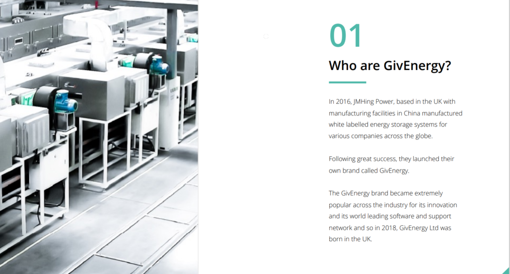
So now we have a line in the sand: around 2016 it all started. I can find very little about what JMHing Power actually made back then (mostly seems to relate to LED’s and such but that may just be what’s left over on the internet about them – 7+ years is a long time for old defunct web pages to stay untouched!)
Now eagle eyes will note the “manufactured white labelled energy systems…” part which may well be where all these other similar devices fit in (the timeline kind of matches) which we’ll move on to.
Similar Devices #
So onto the juicy bits. After hours and hours I’ve a fairly comprehensive list of similar devices to Gen1 Hybrids. I’ve tried to sort by oldest first but there may well be others I’ve missed. I’ve split them in to 2 categories – Suspected White Label & Unknown Relation.
Suspect White Label #
1: Lantrun: #
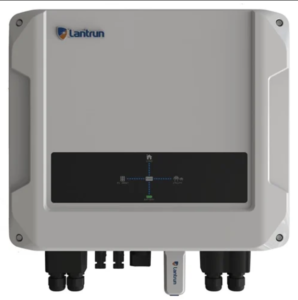
This appears to be the earliest around ~2016, although the archived website suggests they existed back in 2015 this particular inverter may well not have done.
Available in various outputs but the two common ones are the Aegis 3600ES & the Aegis 5000ES.
I can’t however find much reference to these being sold in the UK.
Supporting Documentation:
Lantrun Aegis Manual & Datasheet: Here
Now your all going to say “well it doesn’t look much like the G1 Hybrid?” Well if you go back far enough the G1 Hybrid manual showed the inverter looked like this:

So that’s more than a little similar. The specs also appear to match as well, as does the dongle design & general serial numbering patterns.
Their management portal is still seemingly live so I’m not sure if they are still supporting these?
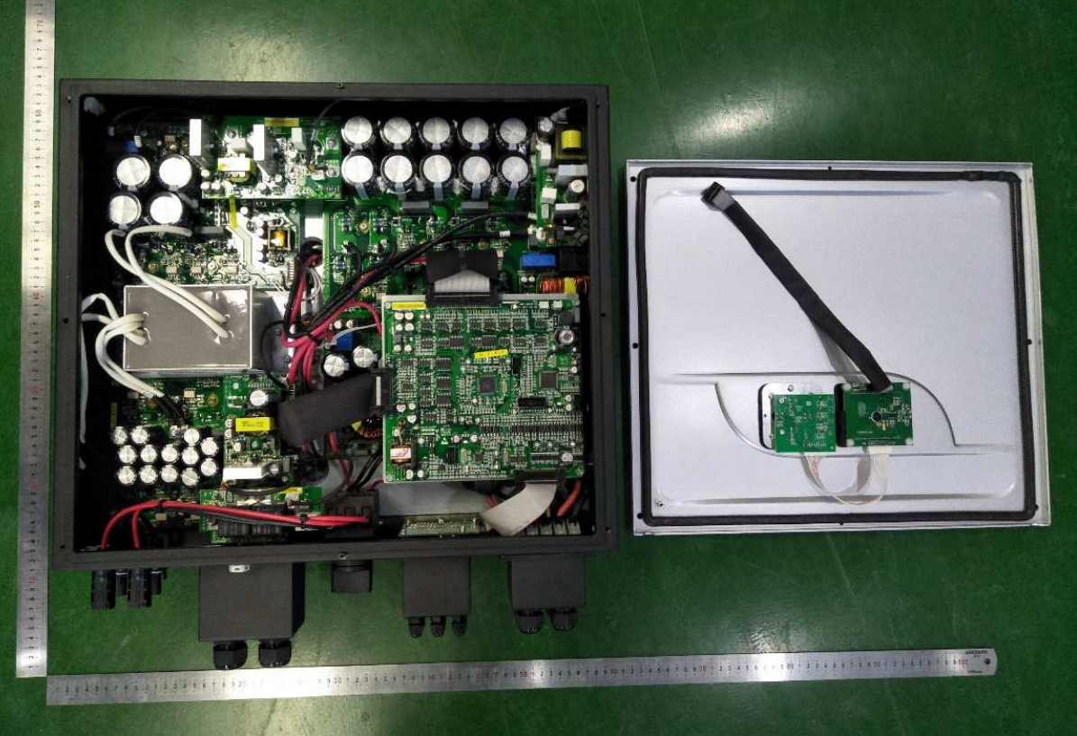
I did manage to find a video of someone taking one of these to bits which has proven quite useful as a comparison.
< April 2017: Givenergy G83 Compliance Certs Signed > #
Certs lodged on the old ENA database allowing the Givenergy/JMHing Inverter to be connected to the UK Grid (some parts of those docs reference Lantrun so that was an easy win for me.)
I’m taking this point in time as the “official” launch of the Givenergy Inverter into the UK.
2: Prime Hybrid Energy #
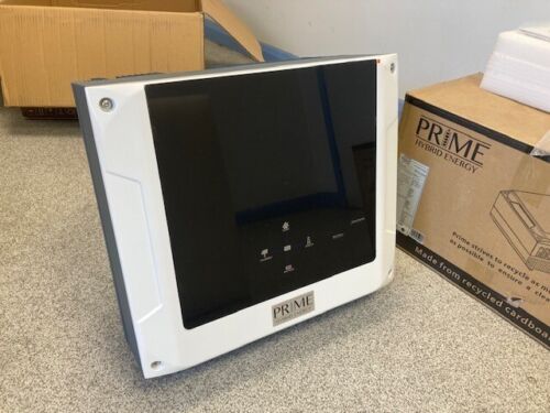
Now these DID in fact make it to the UK in 2017 – the ENA compliance certs are literally dated the same day as the Givenergy ones.
They appear similar to the Lantrun but with a slightly different fascia however the specs are again similar.
Available in 3.6 or 5kW outputs as you’d expect.
There is some information about these, social media groups & the website are still live but little interaction at all with anyone last few years suggests they may no longer be active.
The monitoring portal has also started to show signs of neglect, I’ve noticed the demo portal no longer works and so on…
Linkedin would suggest some of the staff have moved on to Givenergy & I’ve seen evidence online of a Givenergy Dongle working in these inverters to enable control.
Supporting Documentation:
Brochure / Datasheet
Twitter & Facebook
News Article
3: Ladon Technology #
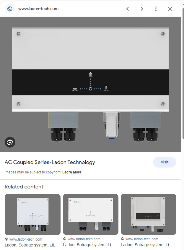
I can track this to around 2019 and as far as I can tell never made it to the UK.
It appears to have been setup by someone who is also fairly involved in GE China – which goes someway to explain why they also list GE inverters as well under product codes. What is interesting is this is the first (& as far as i can tell, only) appearance of the AC coupled inverter being white labelled.
Again similar specs & similar design choices compared to all the others.
The website was still running until very recently. Unsure if this is temporary or not but I can’t find out much about them at all (perhaps they were setup to serve different markets rather than the EU.)
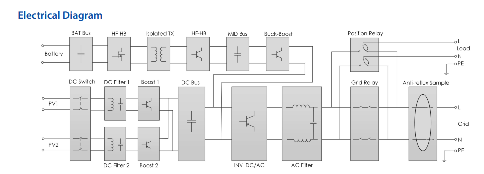
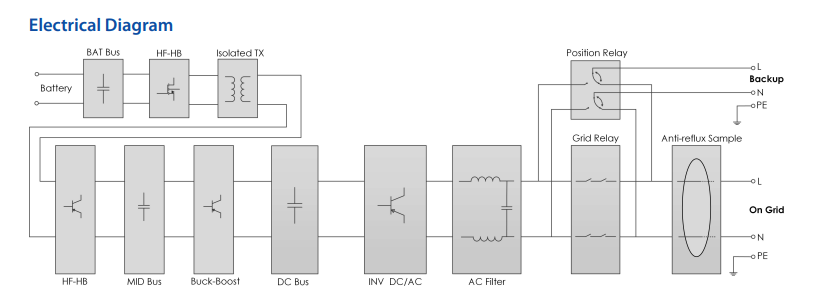
As a stroke of luck, what they do provide is a basic circuit diagram for both the Hybrid and AC Coupled which has proven useful:
Hybrid:
AC Coupled:
Supporting Documentation:
Datasheet – Monitoring Dongle
Datasheet – Hybrid 3600/5000
Datasheet – AC Coupled
Archived Website
4: Energy Storage Australia #
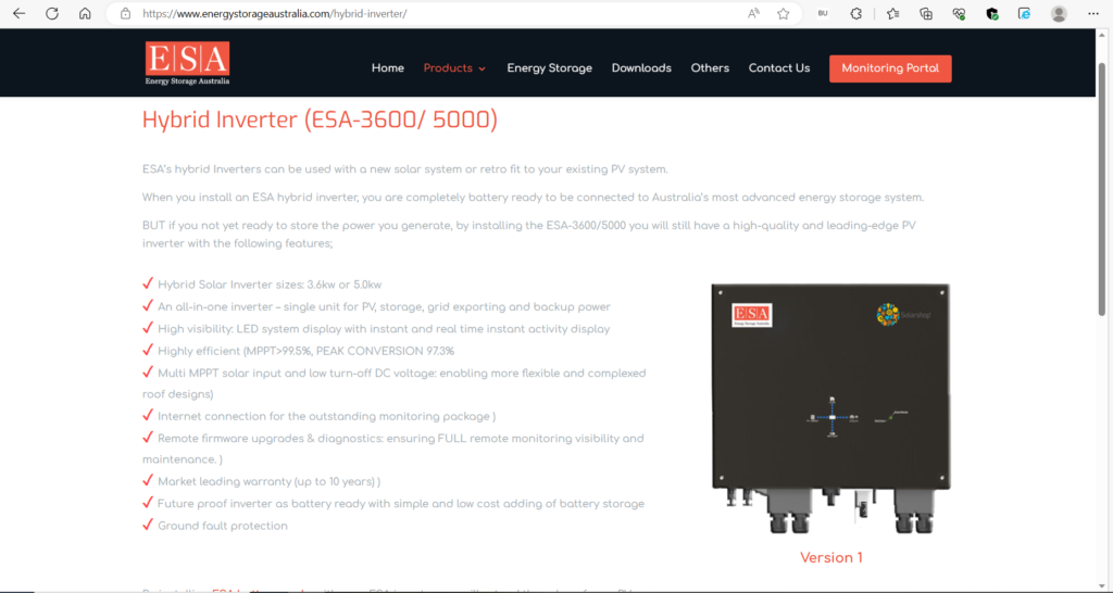
Again you get the idea by now, but this is the first appearance of what we know as a Gen 1 Hybrid aesthetically (albeit in all black) with a different name on the box.
These seemed to make an appearance around 2020 and as far as I can tell only in Australia but again there doesn’t seem to be much about them. Weirdly although the inverter appears black the batteries are not (they look the same as Givenergy) so I suspect this is/was testing the Australian market.
I’m unsure if they are still sold under this brand, the monitoring portal does appear to still work and the URL clearly has “/GivManage/” in the string: Login page – Hybrid Monitor Center
Supporting Documentation:
ESA Hybrid Manual
ESA Hybrid Datasheet
ESA Battery Datasheet
5: Sumry #
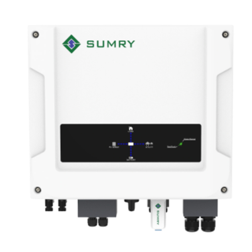
I, like you are getting a bit bored now so I’ll keep this one short. Appears around 2020/2021. Pops up on Alibaba type sites if you dig around. Similar specs to the others (3600W – 5000W) although it does contradict charge rates at times (50A max charge or 3600W, pick one because it can’t be both)
Supporting Documents:
Aegis 3600ES / 5000ES Manual
Product Webpage (Archived)
Unknown Relation? #
Now I’m going to tread lightly here as this is almost impossible to prove one way or another but there are some inverters floating around that bear some resemblance physically to the suspected white label ones but just slightly different enough to not fit in the white label category.
The main thought process for this is based around the product casing being different, the heatsink fins being just a bit different, the inclusion of a screen and so on. Internally they do however bear similarities which I’ll explain below:
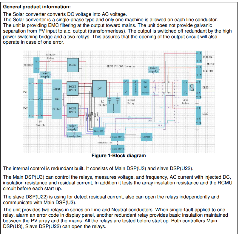
Must (PH1000 Series) #
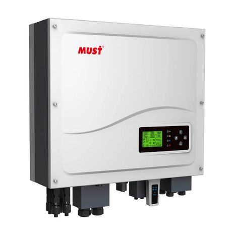
So why do I think this is potentially related? Well externally you can see that the cable entry layout is the same. Now this means nothing on it’s own (there are ultimately only so many ways to bring cables into a square box) but also a lot of the specs appear to be similar (not always identical though) to the others.
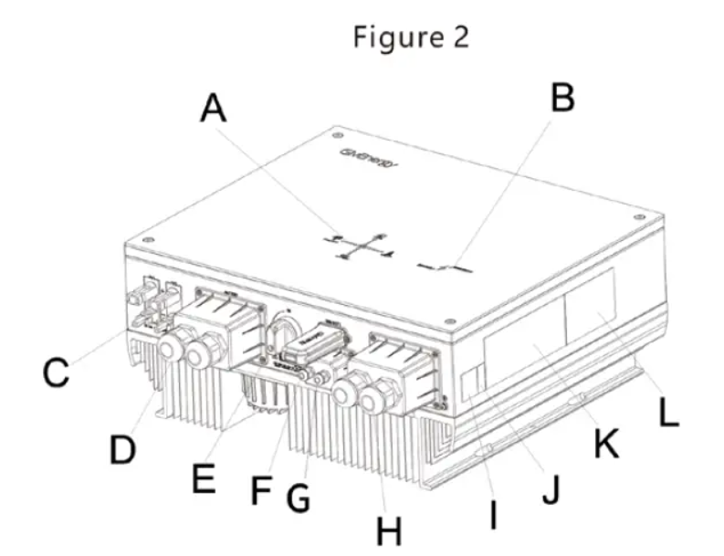
GE Terminals
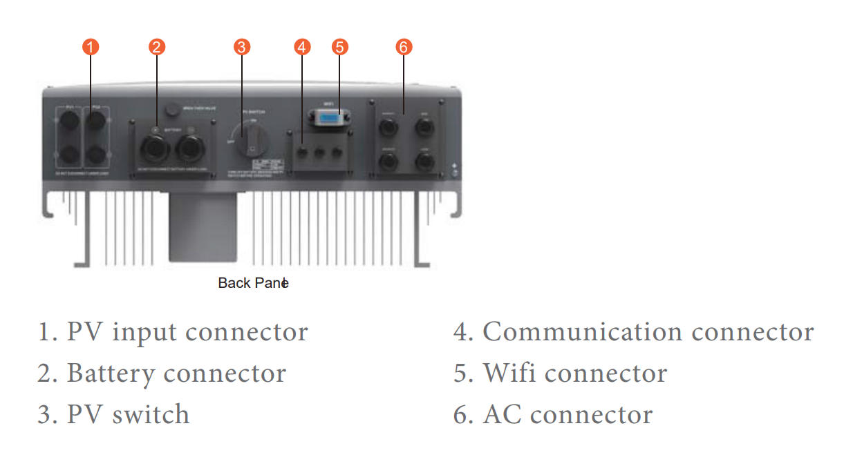
MUST Terminals
The earliest I can find this inverter referenced is a datasheet (under MUST’s “SolarBaba” branding) uploaded May 2017 however it appears to have many different names for some time.
Further datasheets / info are here, here & manual here
These seemingly same inverters also popup as:
Neexgent NG1000
HiZN 3600
MppSolar PH10
There is also a PH1000 “Pro” model which boosts the charge & discharge to 4kW although I can find no imagery of it’s internals to confirm if the design is the same (maybe this is Gen2, maybe it isn’t I just don’t know.)
Anyway,
What was interesting in stumbling across these inverters was the IEC documentation which shows the inverters internals which were surprisingly similar:
Must Internals
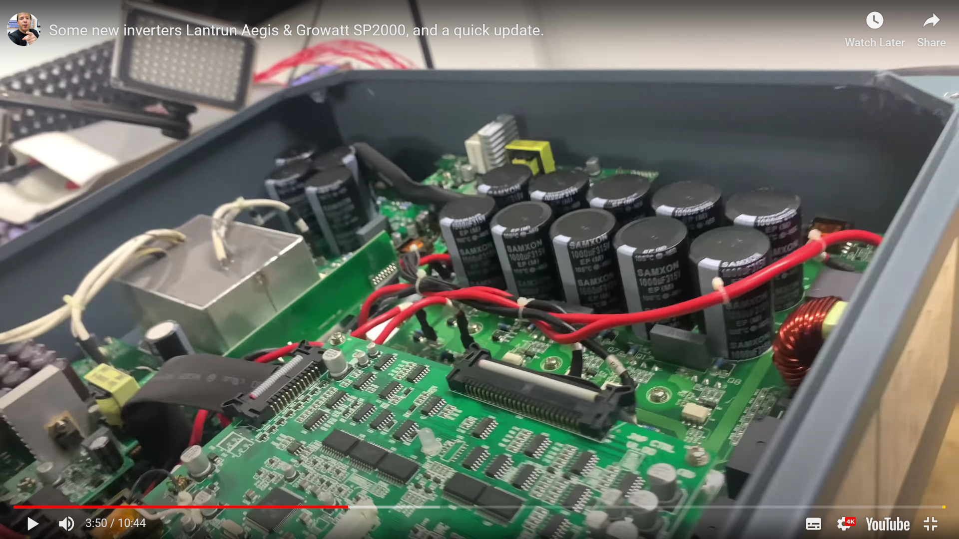
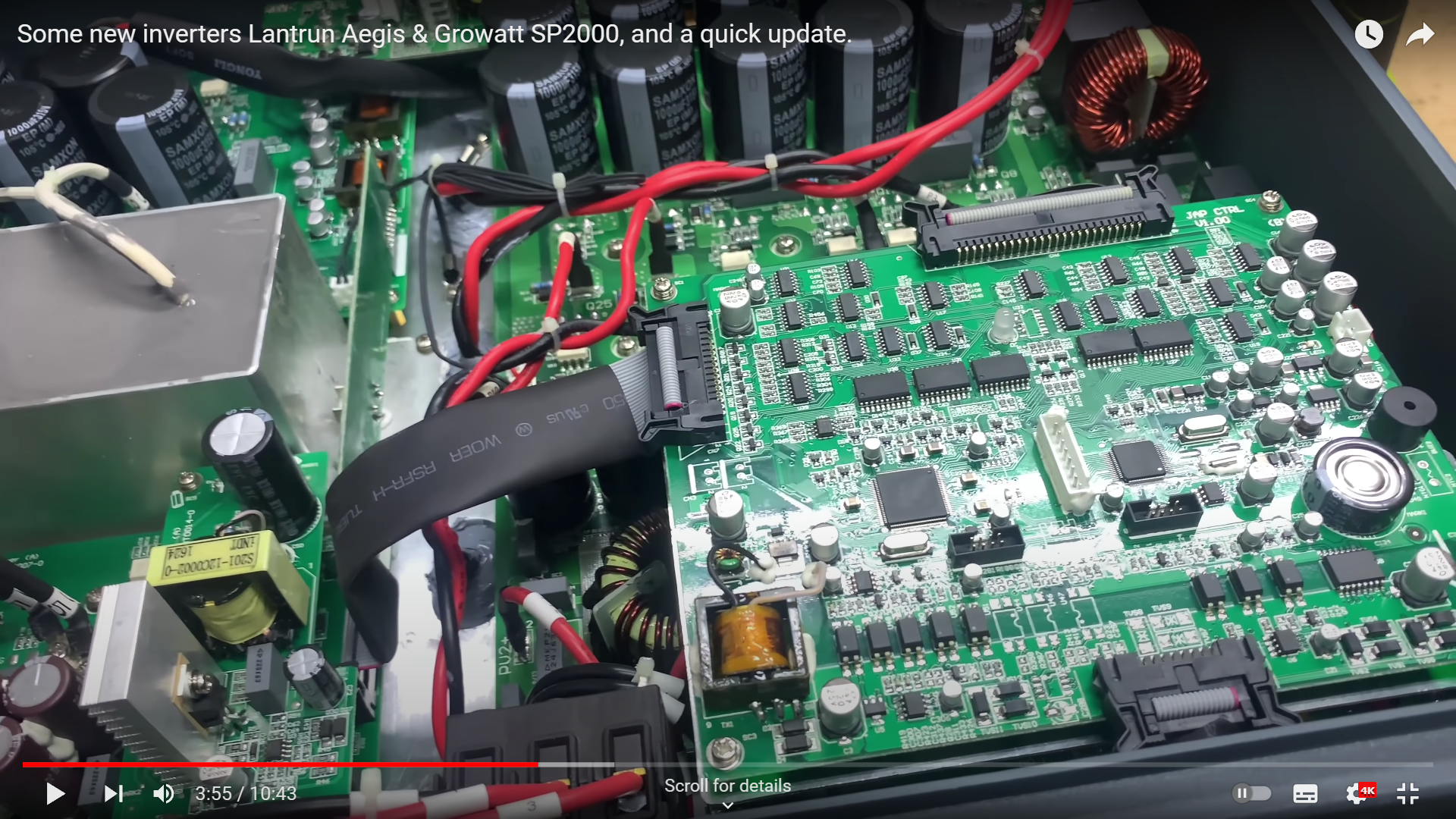
Lantrun Internals
(Best I can do from a video)
Givenergy Internals
It should however be noted that the Givenergy G1 Hybrid (beyond obviously having blue PCB’s) does seem to share at least some of it’s design with all these inverters and as such I’ve used all this discovery to help explain how the inverter works.
Instantly however you can see that the Givenergy inverter has a lot more going on inside with various daughterboards and additions compared to ALL the other designs – hence I must stress they are by no means a direct “copy & paste” with a Givenergy Logo on the front!
Gen 1 Inverter Teardown #
First and foremost: Safety #
Opening the cover of the inverter will instantly void your warranty.
Opening the cover of the inverter will also expose you to high voltages, stored energy (capacitors) and numerous other electrical hazards. Just don’t do it – you don’t need to. All the pictures are all here.
You have been warned.
Useful Diagrams #
Now all that is out of the way I’m going to use 2 Circuit diagrams to try and unravel how the Gen 1 Hybrid works. (I couldn’t just start the article with these two diagrams as nobody would know where they came from or where I had got them from)
First is the basic system design found from the Ladon-Tech / Lantrun Datasheets:
And secondly is this much more in depth diagram from the MUST inverter (which I’ll use to a lesser extent given the unknown connection it has to the others, but appears relatively “right” in how the inverter is laid out, excluding the EPS supply loop back that is present (E.M IN & E.M Out))
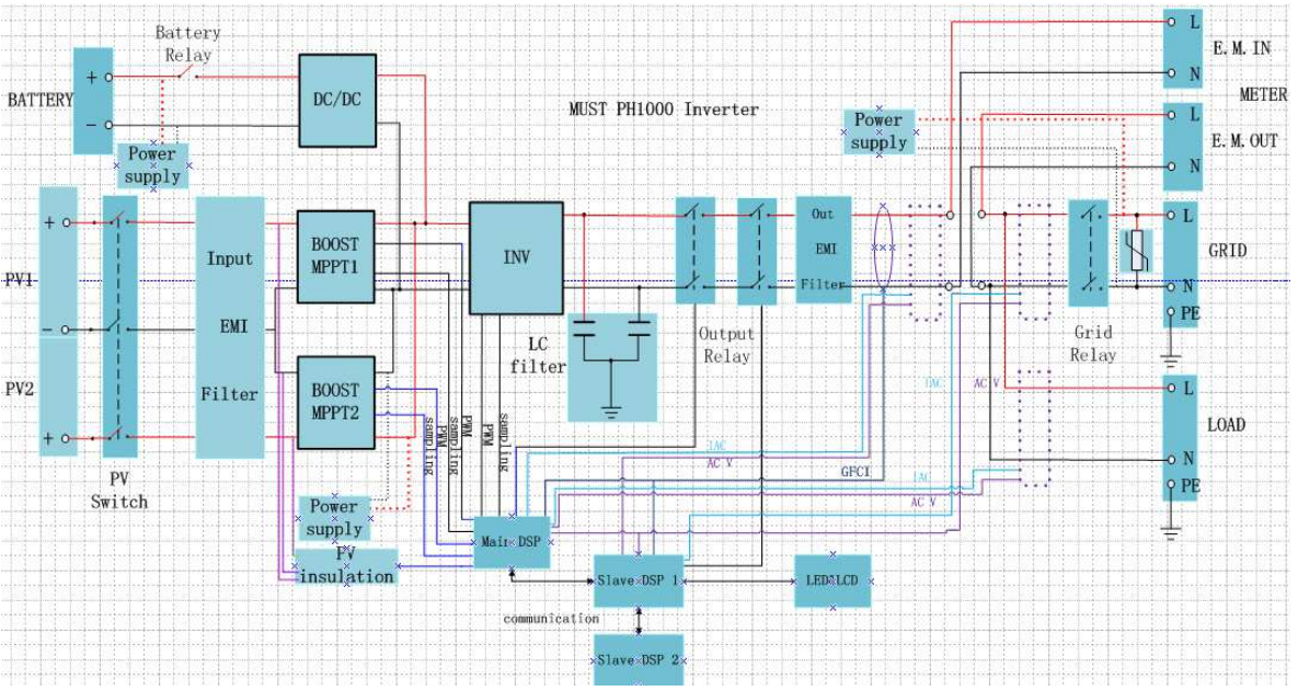
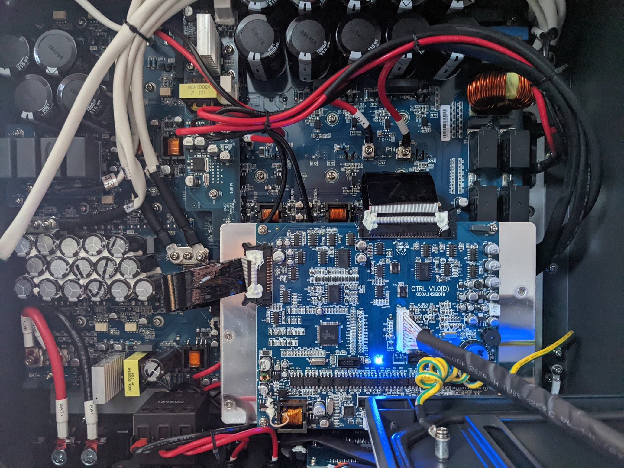
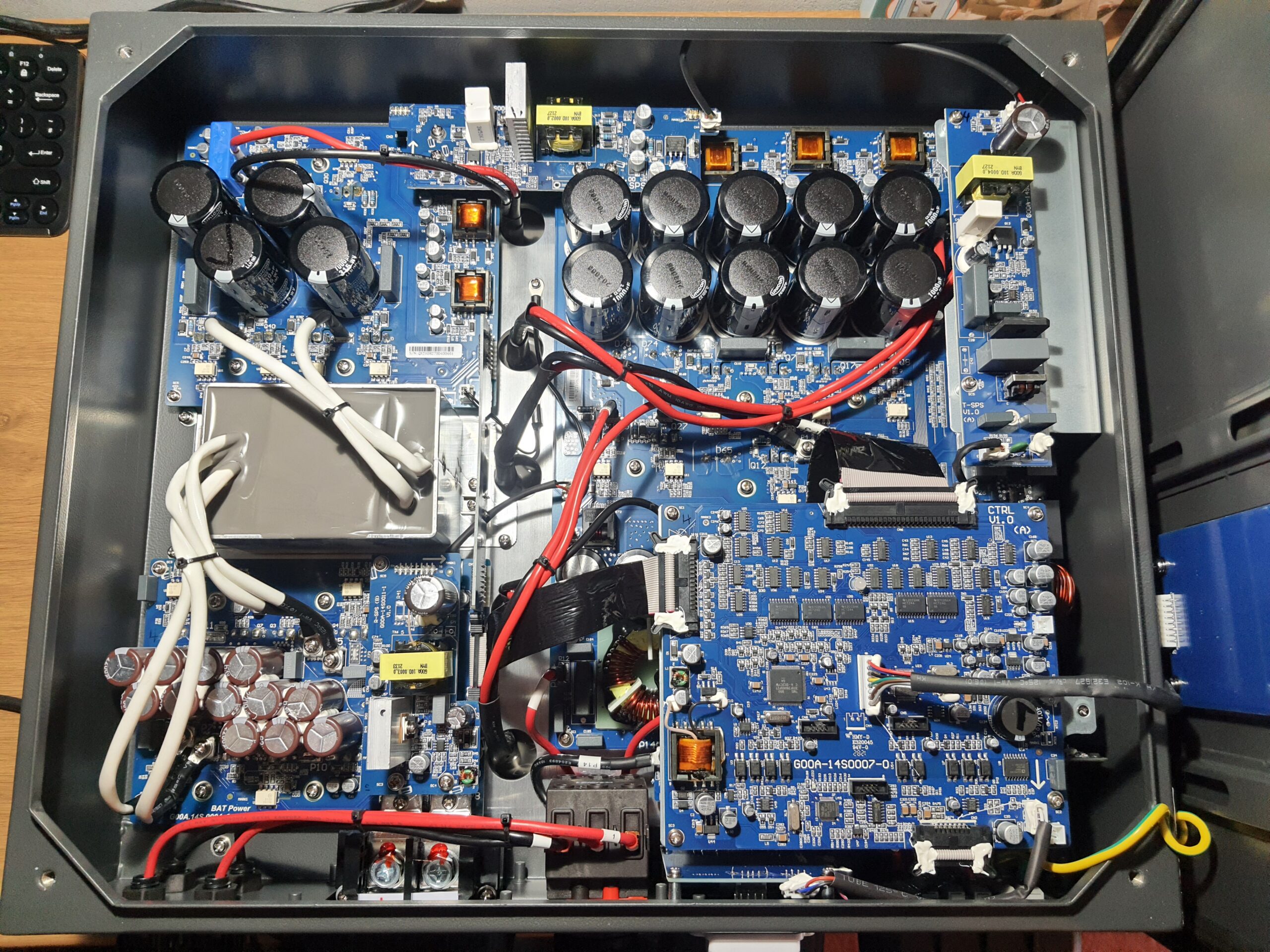
Internal Gen 1 Main Overview:
#
Note: this is a 2021 inverter, things may have changed since.
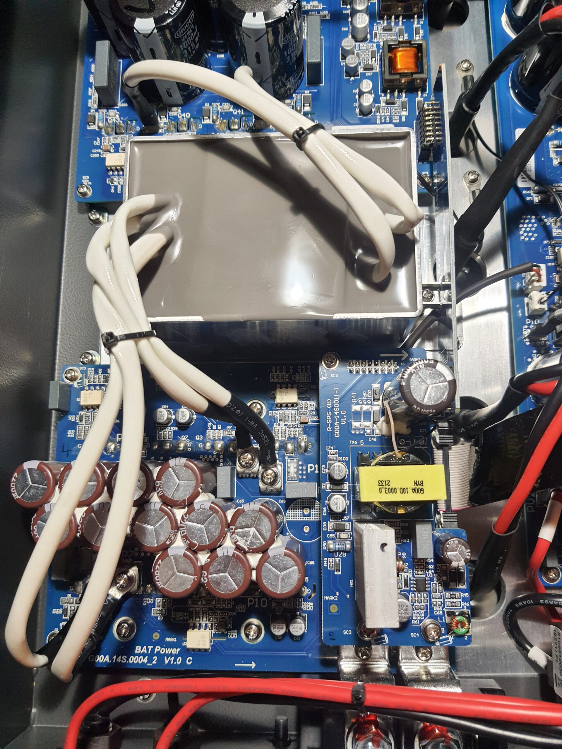
So, this is an overview of the main components.
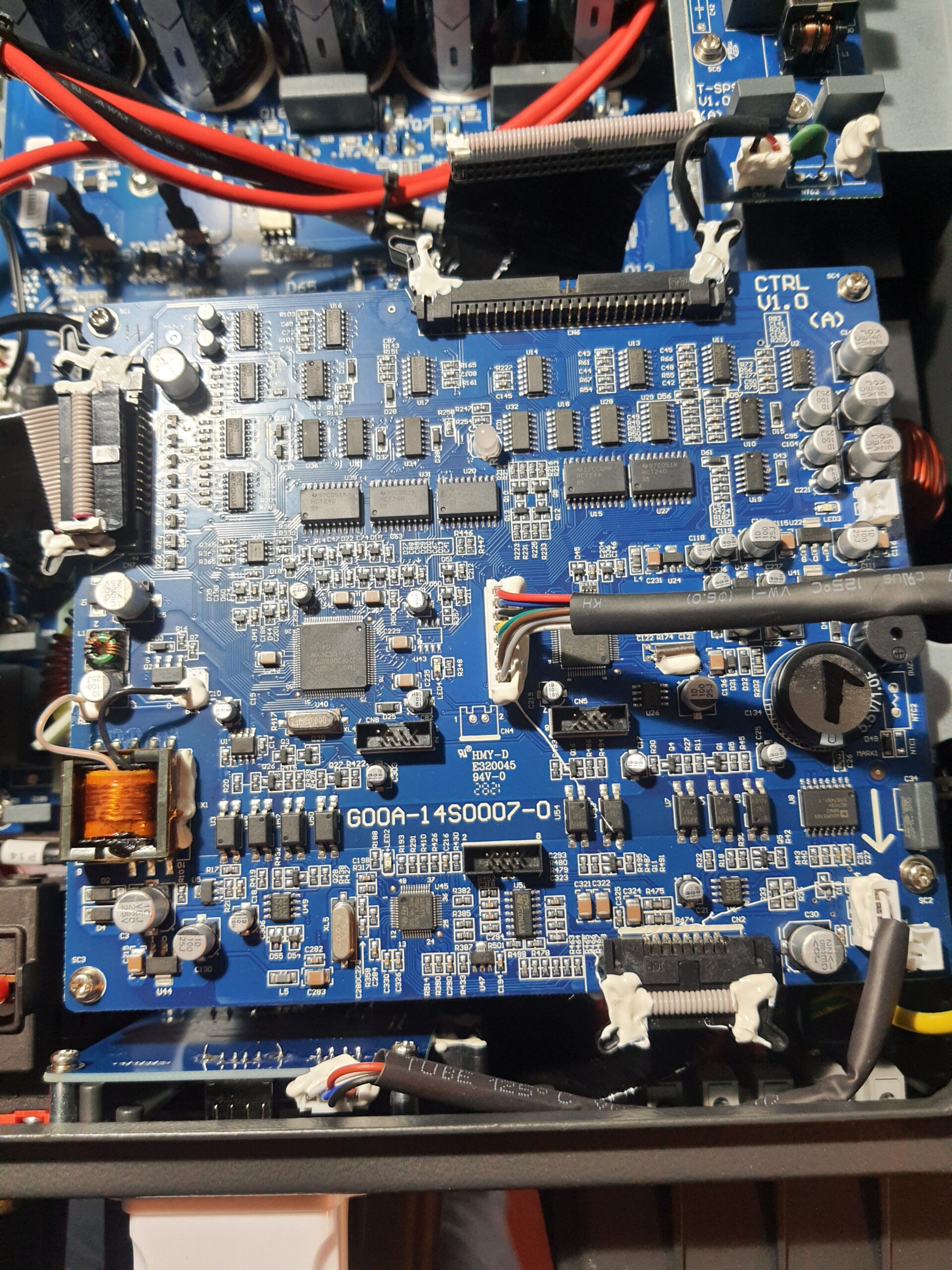
Starting at the bottom right, you have the main controller board (G00A-14S0007-0).
Bottom left we have the Battery Charger & Discharger Board (“Bat Power”) which outputs to the battery terminals.
Above that we have a battery isolation transformer (Grey resin filled) with connections from the upper Power board to the battery board. (No markings but if MUST IEC parts list is correct then possibly Class F – 7.5mH)
Above that we have another Power board which links to one of the 5 inductors and also bridges across to the main board on the right hand side linking the PV to the battery. Also note that just to the right of the transformer is a small link PCB which links from the upper battery board to the lower – the tracks on this are very small so I assume this is data related rather than power transfer.
Channelled down the centre of & the through the backplate into inverter heatsink are 5 inductors. You can also see 2x Temp probes in this channel. One between the top 2 inductors & another between the second & 3rd. (Inductors may be a mix of Class B 1.5mH & 1.03mH if using MUST IEC parts list)
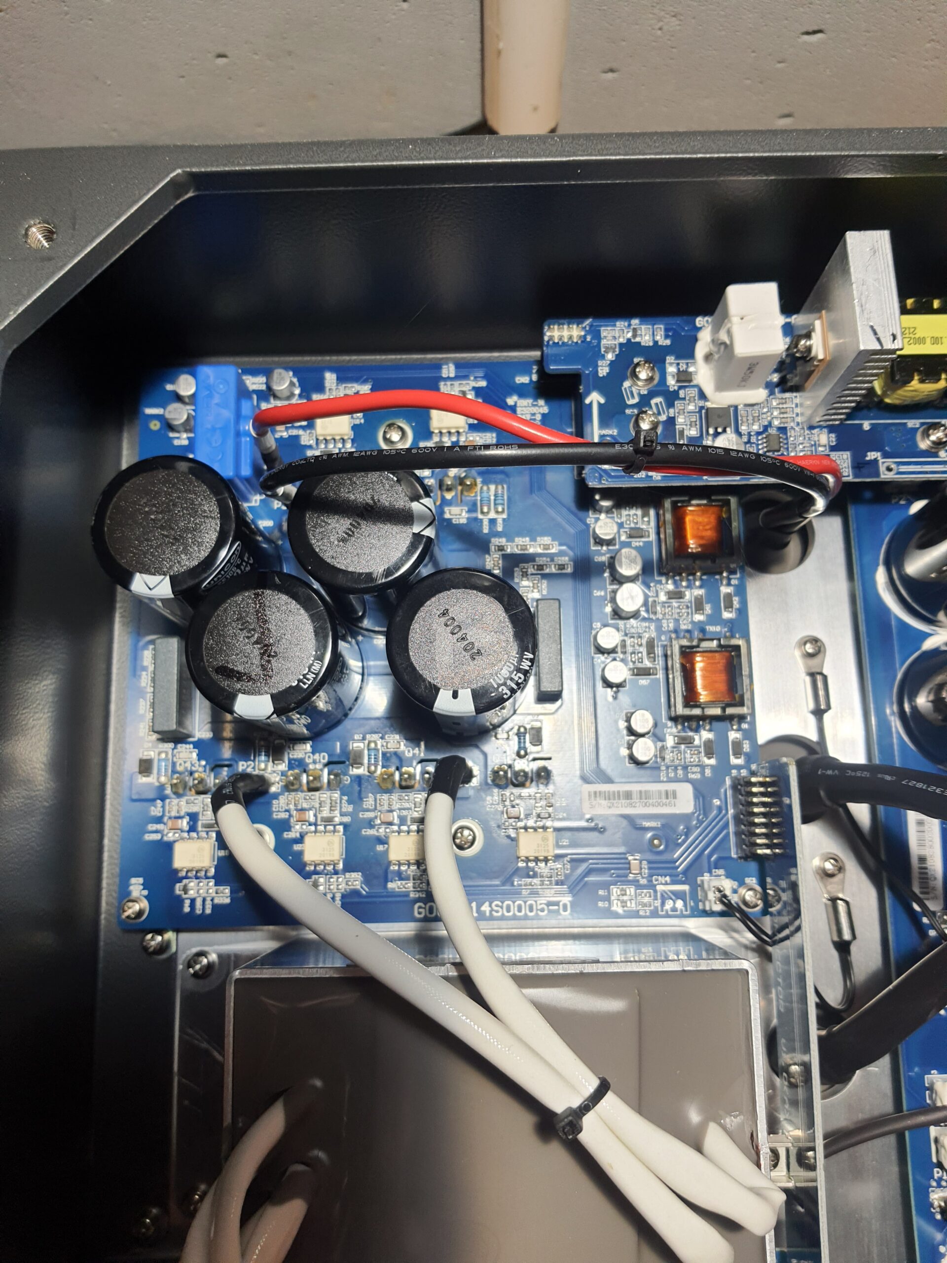
Finally to the top right we have the Main Board (MB Power) which is mostly obscured by the controller so lets get that out the way:
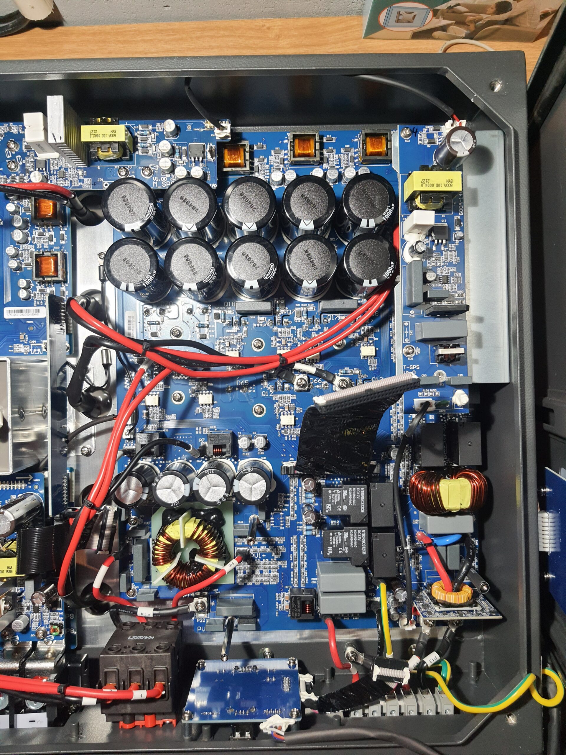
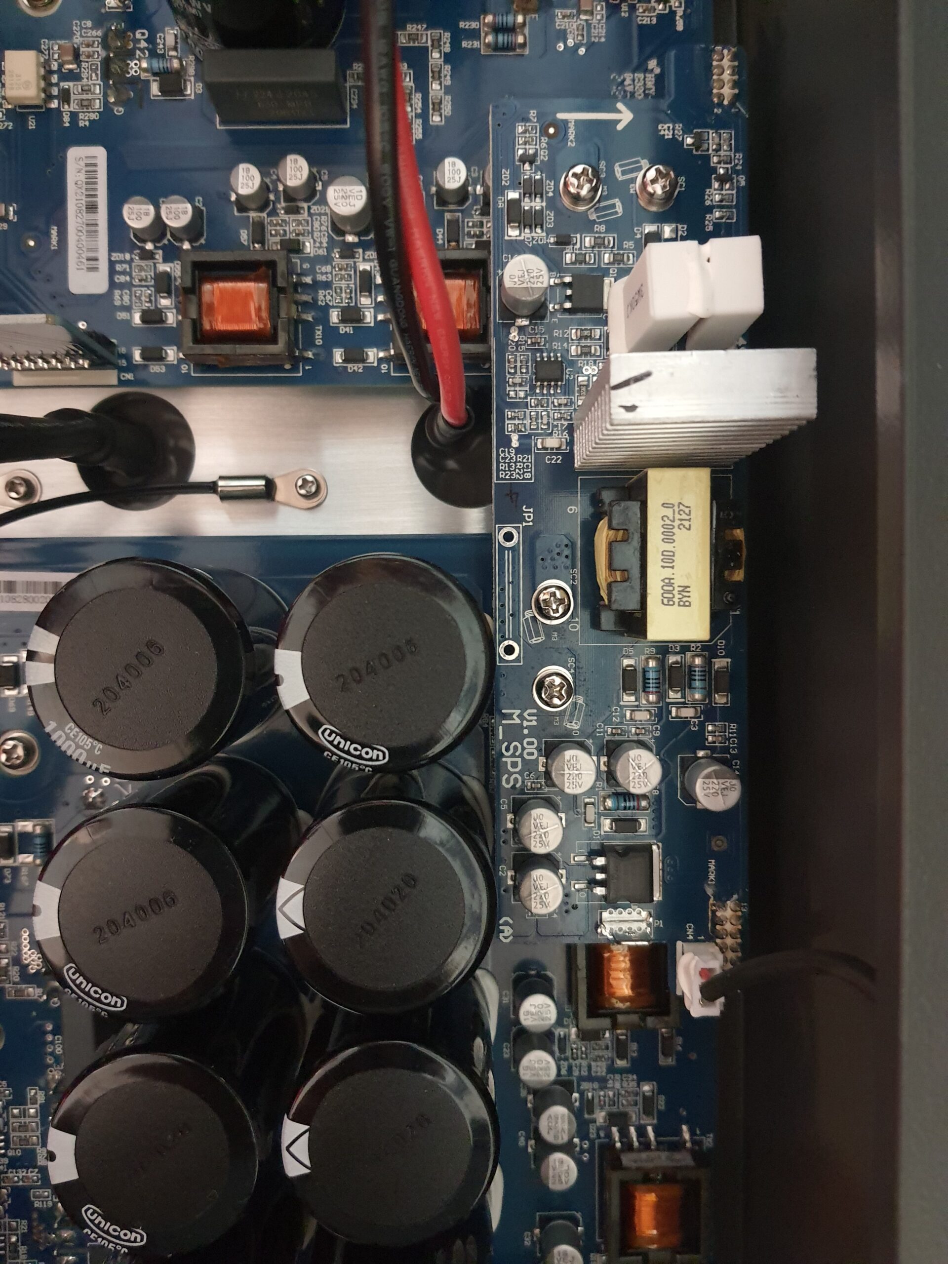
So, now the controllers gone, you can see bottom left where the 2x PV strings come in. Note that the negative of both strings is combined at the isolator (only 3 poles.) You can see the negative black cable connect to the main board just above and to the right of the main isolator. Strings 1 & 2 connect to terminals PV1+ & PV2+ and have a small bank of PV input capacitors (Lelon Brand 390uF – 315V)
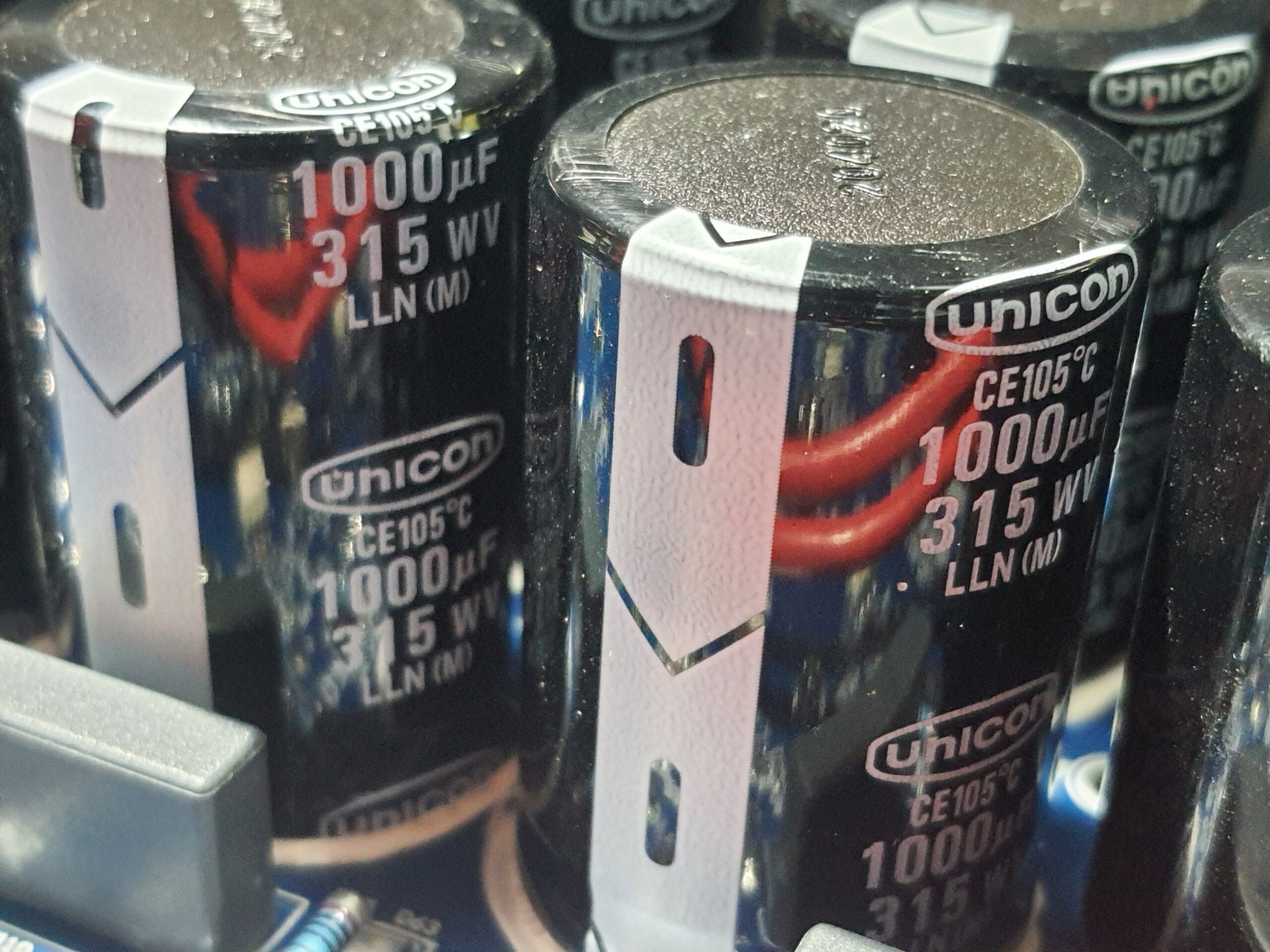
3 further inductor connections can be seen linking in at the mid level & top right along with a capacitor bank (Unicon Brand 1000uF – 315V)
Bottom right is both Grid In Out & also the EPS connections so let’s look a bit closer at those:
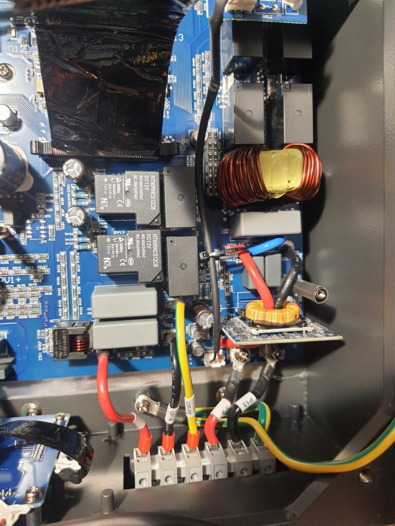
The left hand terminals (OP-L, OP-N & OP-PE) are the EPS supply.
The right hand terminals (P9 & P13) are the Grid connections where all the power flows in/out.
Directly above where the EPS Earth connects to the PCB are what I believe to be the Grid relays. These link the incoming AC to the EPS under normal operation & throw over when Grid supply is lost to prevent back feeding the Grid.
There are various current monitors dotted around (small black cube next to smaller light grey relays (what I suspect to be the EPS Neutral to Earth bond relays) – labelled HCT3, many of which are Tamura L18P series (1 for the EPS supply, 2 further ones for the PV Strings)
There is much more to investigate in these areas but as an overview I think that’s enough. (There are all sorts of ancillary boards & SPS boards to unravel)
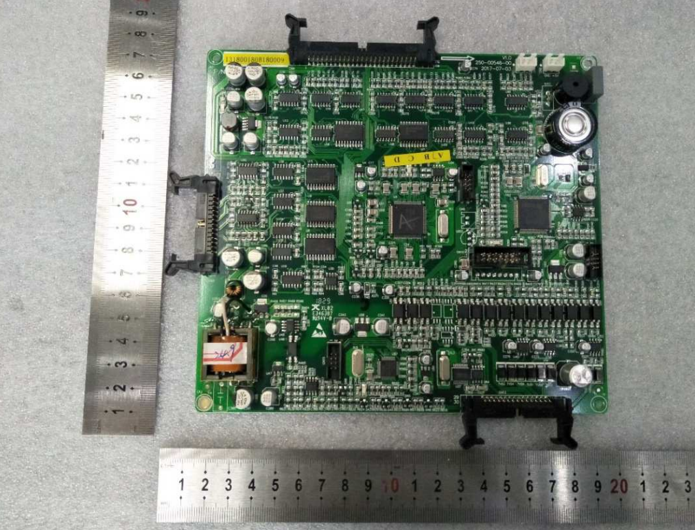
Control Board: #
This (obviously) controls the inverter but also provides a link to many other boards:
The USB dongle (via a daughter board) linked by the bottom connectors – you can just see the dongle poking out at the inverter still.
The Battery Board by the left hand connector
The Main Board by the top connector
The inverter front casing lights – the connector in the middle.
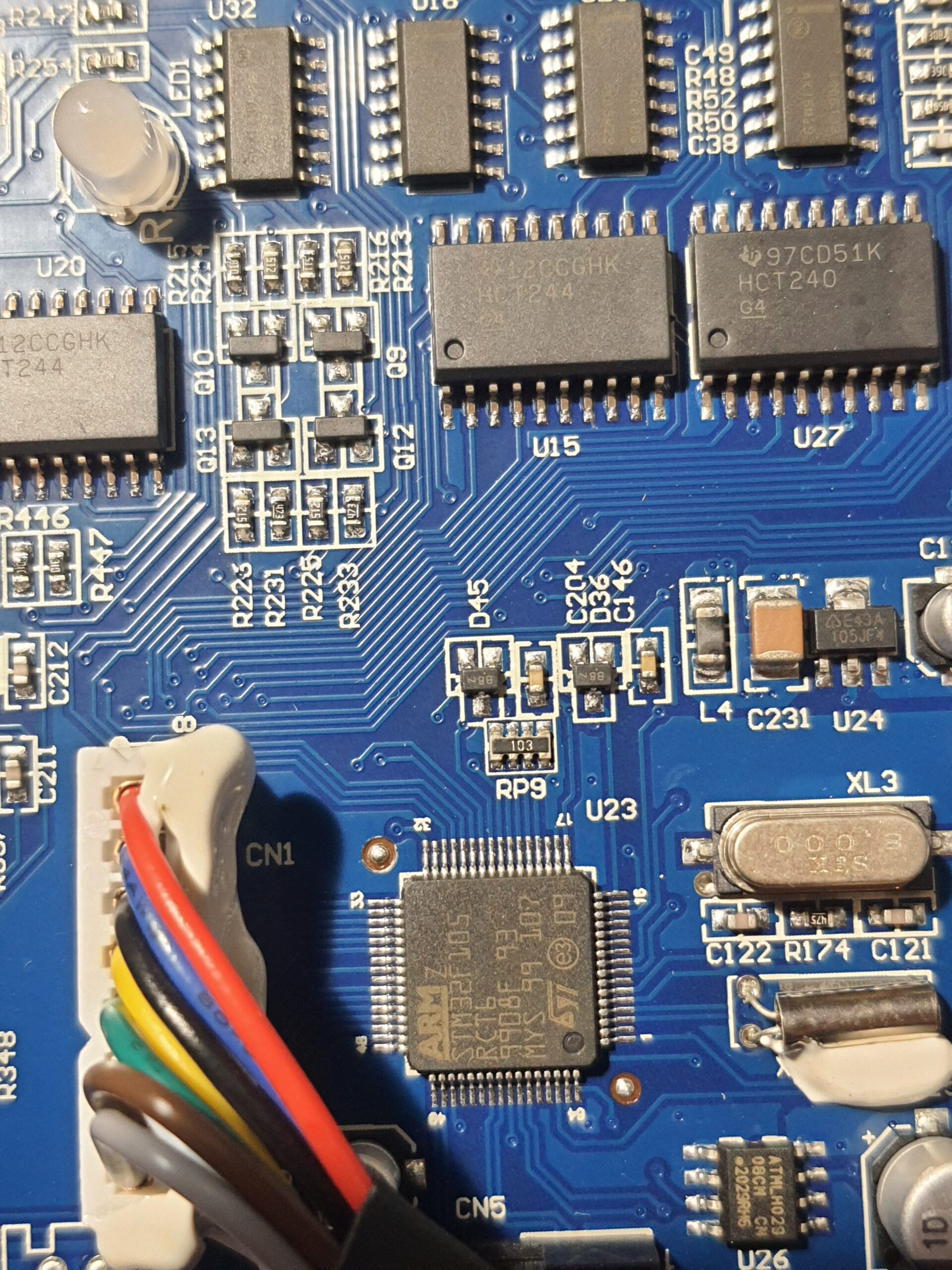
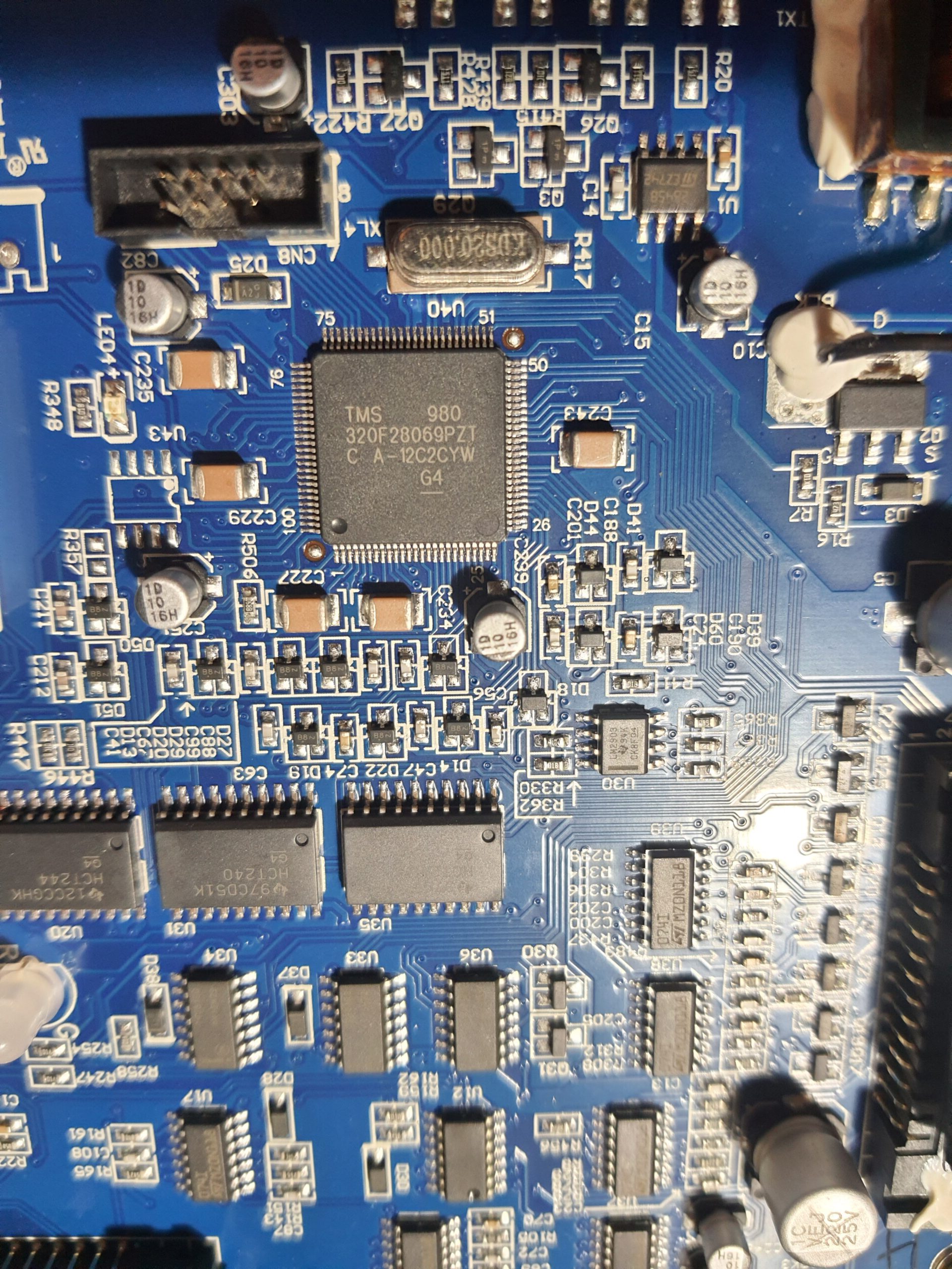
A closer view reveals the controller is using:
DSP (or “U3”) – Texas Instruments TMS320F28069PZT running at 90MHz
ARM1 (or “U22”) – STMicroelectronics STM32F105RCT6 running at 72MHz
ARM2 (or “U57”) – STMicroelectronics STM32F103C8T6 running at 72MHz
Now the “Uxx” numbers don’t quite match up but It looks to be that the chips are in Master/Slave arrangement which ties in with what is in some of the MUST documentation:
Battery Boards #
Battery Board Lower:
The battery lower board contains a capacitor array – 63V 220uF. I couldn’t see a brand on these but the viewing angles aren’t great – possibly Elna based purely on the colour)
The capacitor ratings being 63V would suggest that this board is (as you’d expect) the LV DC side.
Connections from the Isolation Transformer and outgoing terminals to the battery can clearly be seen.
I need to spend more time on this board, particular around & under the ancillary board above it. (for example I couldn’t see what I expected to be a battery disconnect relay or anything current monitoring related on this LV DC side suggesting that the battery current readings may be being done from the upper board)
Battery Upper Board:
Top left, in bright blue is a current transducer (LEM LAH 25-NP) – rated to 55A max reading (these are closed loop Hall effect type)
Below that is another capacitor bank this time Unicon again (1000uF 315V) along with a link to another inductor.
Now top right is a link board between battery upper and Main Board. There’s a lot going on here & unless there’s a big bus bar hidden on the underside under it I suspect this is the sole link from the PV/AC to the battery side and is likely the weak link as to why the charge rate is fixed at 2600W. (It kind of looks like the standoff pins are actually forming part of this link – they are set into/on pads – To investigate)
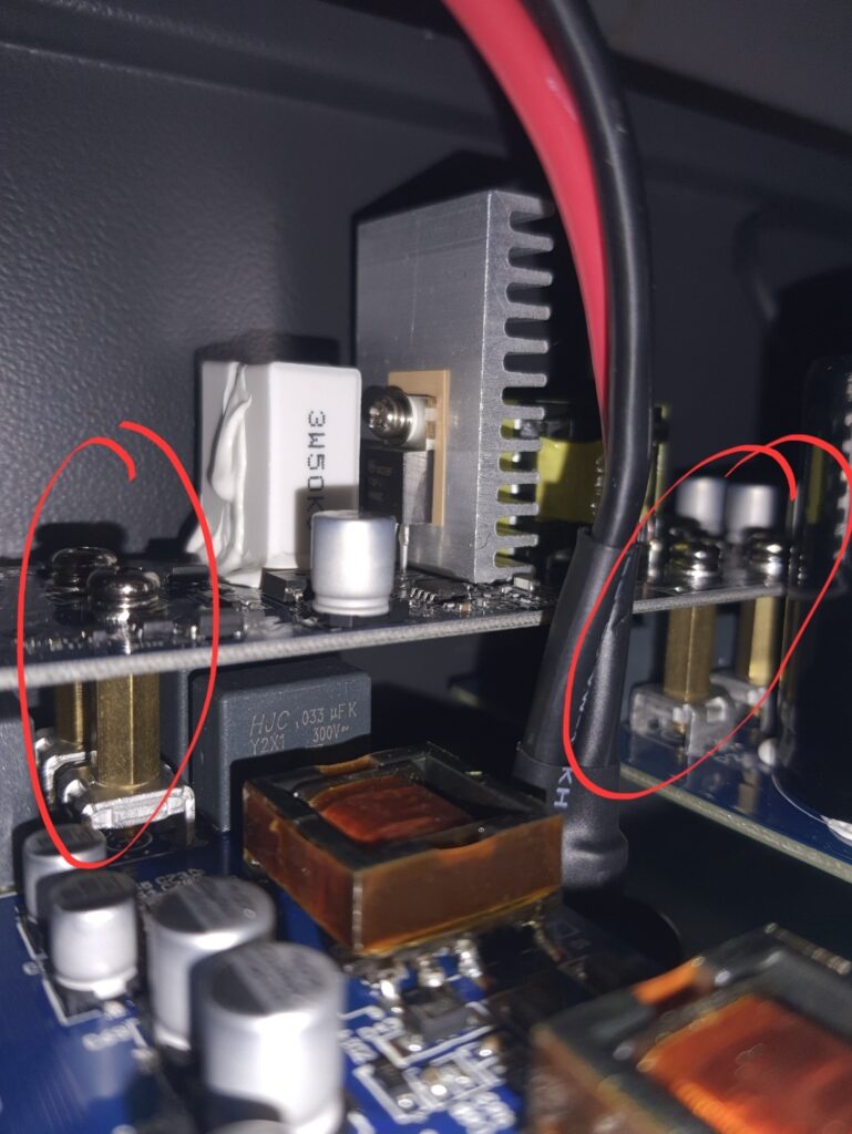
Note standoffs that appear to bring across power to the upper battery board from the main board.
That’s about it for now. As I work my way through in detail I’ll update as I go….
Gen 1 vs Gen 2 #
Now I know what’s coming “but what about Gen2” – well, basically I don’t have one. (No don’t go opening yours, warranty, death and so on…)
I have managed to acquire a pic of one and it is fundamentally different internally (the isolation transformer is gone/moved to an inductor pocket possibly, which also now seem to be on the RHS rather than the middle?) which would suggest was at least partly related to the main charge rate bottleneck.
The main board is now much more of a “main” board rather than the scattered Gen1. There are considerably fewer ancillary boards and links needed across this design.